GPIO Tutorial: Part2 - PWM
The KIWI boards are versatile and cost-effective single-board computers that have become increasingly popular in the industry and DIY communities. Much like the Raspberry Pi, the KIWI boards also feature Pulse Width Modulation (PWM), a technique that enables precise control over the output of digital signals.
What is PWM?
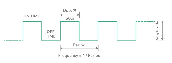
Pulse Width Modulation is a method used to control the average voltage of a signal by varying the width of its pulses. It allows for regulating power supplied to a device or component by adjusting the time the signal is in its high (on) state versus its low (off) state.
How does PWM work on KIWI boards?
The KIWI boards, are equipped with built-in hardware support for PWM on specific GPIO (General Purpose Input/Output) pins. The PWM functionality is facilitated through a dedicated PWM controller, allowing you to control the duty cycle of the signal.
The duty cycle represents the percentage of time the signal is in the high state during each period. Changing the duty cycle can effectively control the power or intensity of connected devices.
Applications of KIWI boards and PWM
1. Precision Control
PWM on the KIWI boards provides precise control over the output voltage or intensity, making it suitable for applications where accurate adjustments are essential. PWM is widely used in robotics and automation to control the speed and direction of DC and servo motors.
2. Energy Efficiency
PWM is an energy-efficient control method that regulates power by rapidly turning the signal on and off. This is advantageous for battery-powered devices. PWM is employed on the KIWI boards to adjust the brightness of LEDs in various lighting applications, from ambient lighting to display backlighting.
3. Audio Output
PWM on the KIWI boards can generate audio signals. It can produce different tones and pitches by modulating the duty cycle, making it useful for sound generation projects like synthesizers or tone generators.
4. Industrial use
In applications requiring precise temperature control, PWM on the KIWI boards regulates the power supplied to heating elements. It is also used to regulate the charging of batteries in solar power systems, optimizing energy transfer and storage.
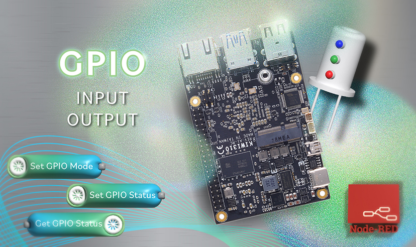
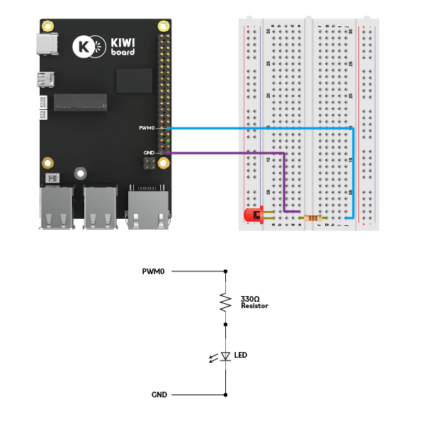
KIWI boards GPIO PWM
For a basic LED demonstration, connect the longer leg (anode) of the LED to a 330ohms resistor to PWM0 (pin32) and the shorter leg (cathode) to the ground (GND) pin. This uncomplicated setup showcases the GPIO PWM output functionality of the KIWI boards, illustrating how it can effectively control connected components through its GPIO PWM capabilities.
In order to set up the sample flow for Node-RED, please refer to our earlier publication. For more information, consult KIWI310's middleware documentation, which is available on Github.
- On the Node-RED's GPIO flow, verify that the node to Set PWM0 is enabled and set the desired frequency in a range of 1K~200K.

- Set the duty cycle in a range from 0 to 100%
.png)
- To read the status, frequency, and duty cycle, use the nodes "Get PWM State," "Get GPIO Freq," and "Get GPIO Duty," respectively. The data will be shown in the debug section.
.png)
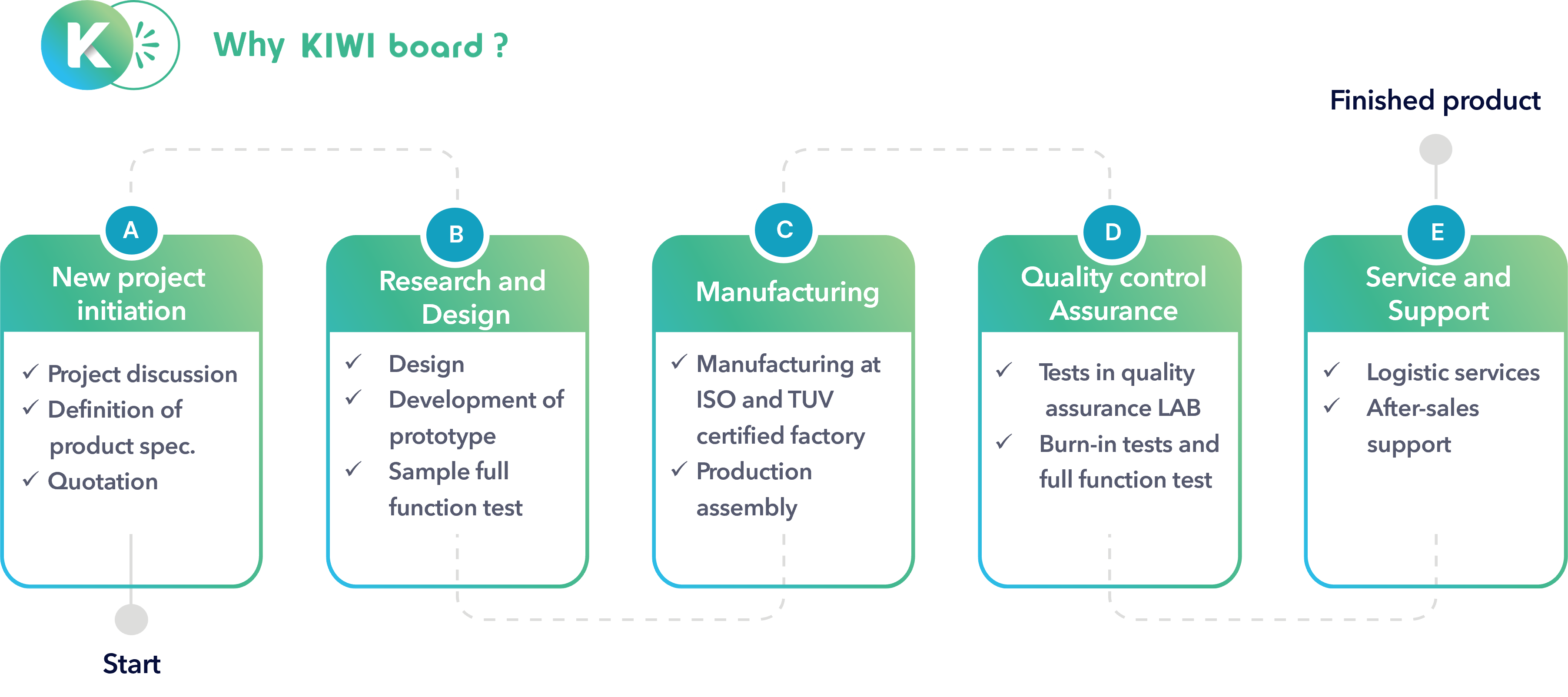
Why KIWI board Solutions?
Pulse Width Modulation on the KIWI boards is a potent tool for achieving precise control over connected devices. Whether you're working on robotics, lighting systems, or audio projects, understanding and utilizing PWM can enhance the capabilities of your KIWI board-based projects. Experimenting with PWM opens up possibilities for creativity and innovation in electronics and digital control.
About KIWI board
KIWI board is a complete solution provider, supporting all aspects of your project, from hardware to software to system integration, to keep your application running securely, reliably, and at peak performance. KIWI board builds its products for high reliability, performance, security, scalability, and versatility. So, customers can expect a long lifespan, quickly adapt to evolving system requirements, and adopt future technologies as they emerge.
Next steps
Ready to talk about your projects with a KIWI board expert? Contact us
Want to hear more from KIWI board? for our newsletterSign up
Or request a quotation
.jpg)